|
 |
|
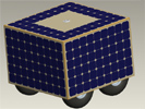
This is a complete, front to back, CAD design of our robot in Pro/Engineer. To provide a sense of scale, the robot measures (approximately) 4x4x3 feet. It is difficult to convey here in this image the fascinating ways in which the panels capture light and change their shade.
|
|
|
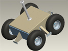
When the solar panel box is removed, the robot chassis is revealed. Shown here is the 20" tire configuration. The outriggers on the four walls are the support and attachment points for the solar panel box. The tube sticking out the top is also a support for the panel box, but is also a mast to route wires and antennae to the outside of the robot.
|
|
|
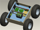
Remove the chassis lid and the supporting arms for the panel box, and you can get a look at the interior of the robot. The blue sections are foam insulation. The large blocks in the middle are the Li-Ion batteries. On one side of the divider are the robot's electronics, the other half may be used for payload.
|
|
|
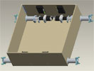
Take out most of the electronics and insulation, and you are left with a stripped-down version of the rolling chassis, shown here with 20" tires. To provide a sense of scale, the chassis box inner dimensions are 27" x 28". The black boxes mounted to the wall are the motor controllers from Advanced Motion Control.
|
|
|
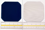
The solar power of the robot comes from SunPower's A300 solar cells, rated for 20% efficiency. Each cell can produce about 3 watts in full sunlight.
|
|
|
Pro/E model of the wheel and hub assembly, sans tire.
|
|
|
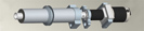
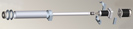
Pro/E model of the drivetrain assembly, without the wheel.
|
|
|
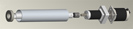
Exploded Pro/E model of the drivetrain assembly, with the mounting brackets hidden.
|
|
|
Exploded Pro/E model of the entire drivetrain assembly, including the mounting brackets and other hardware.
|
|

|
Exploded view of the entire drivetrain assembly, from motor to gearhead to driveshaft to wheel to rubber, with all associated hardware. Full sized image (1920x540 pixels) here.
|
|
|
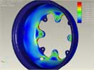
Mechanical finite element analysis of the wheel design when subjected to its highest torque stress load. Because the wheel and load are symmetric, only one-half of the wheel was analyzed.
|
|
|
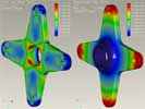
Mechanical finite element analysis of the hub design when subjected to the same high torque load.
|
|
|